Project 2 Video
Video Link
Monday, November 28, 2016
Sunday, November 27, 2016
Project 2
01 Introduction
To expand on the typology of the first project, this second
step involves developing an adaptive shading system to augment the original
surface. The model suggests a kinetic device for directional shading at all
hours of the day. The proposed system would involve mechanized actuators and a
flexible mesh scree. This system could extrude toward this suns position while
opening or closing the aperture accordingly. The project also uses a genetic
algorithm to optimize its final form.
02 Modelling Process
The model is based from the diagrid typology. The surface
diamonds (which would be the mullions on the original surface) are extruded to
create the shading pockets. These extrusions must then be mapped to the
location of the sun, which requires the creation of a sun arc.
03 The Sundial

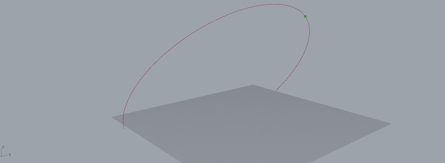
While there are other programs such as DIVA that have sun
angle generators, these programs run slowly and heavily. To take less energy, I
created an arc using angles for sunrise, noon, and sunset of the latitude of
the project for a given day of the year. The sundial also evaluates a point
along this arc that will be our sun position.
04 Face Vectors


A diagrid is applied to a surface at the center of the sun
arc. This will be used as the base of the system. To connect the extrusion to
the angle of the sun, vectors can be made from the centroid of each diamond to
the sun position point.
05 Scaling


The diamonds can then be scaled as a function of their
proximity to the sun.
06 Lofting


After this the scaled diamonds are moved along the sun
vector. The distance of each diamond’s move is determined by the cell’s
distance to the central cell. The moved surface can then be lofted with the
original un-scaled diamond to create the geometry of the shaders.


The shaders adjust their orientation and scale factor based
on the angle of the sun throughout the day.
07 Fine Tuning


The amount of difference between the extrusions’ length can
be massaged by adjusting the first distance component’s difference function.
This effectively increases or decreases the difference between all extrusions.
At a certain point the curvature gives a smoother curve that is the desired
look of the shaders. To find this optimal point of curvature could take a lot
of manual adjustments to find, so I implemented the Galapagos evolutionary
solver to analyze the difference of list items for the extrusions. It aims to
reduce the difference between successive items, thus giving the optimal soft
curve for the overall geometry.
08 Application
Finally this system can be affixed to the original geometry from the first project.

Monday, October 31, 2016
Sunday, October 30, 2016
Project 1
01 Introduction
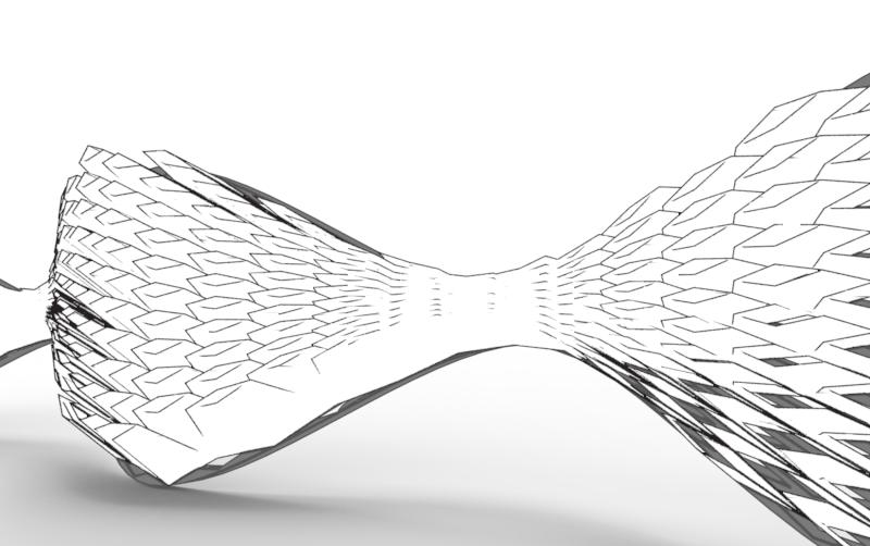
The KAFD Metro Station, by Zaha Hadid Architects is clad in
a mirrored skin of tri-level diagrid shaders. The diagrid extrusions demark the
location of internal metro platforms or levels, however the building skin will
be the focus of this project. On each side, it consists of two tri-part screens
with one quad-part screen between. Each of these diagrid mullion extrusions
sits on a plane curved in and out in the y-direction and tapering in and out in
the z-direction. From these, correspondingly curved ceiling planes extend back
to the next level of screens.

Project Render
02 Modelling Process
To recreate these complex, yet conveniently symmetrical,
surface geometries would take several steps: First to create the curved line
work of the outer surface contour, next to extrude this line work into a
surface, and finally to create and extrude the diagrid pattern across this
surface.

Screen Section
03 Line Work
Begin with a line of defined (easy to work with) length 30’.
Next divide the line into six segments and use these points. Next cull every
other list point and translate the central group up and out in the y-direction.


These points can then be interpolated to create the contour
line. Because of the more complex selection of points for the mid-level screens,
more data organization is necessary to merge the points’ data structure in the
correct order.


04 Surface Creation
After setting the line work, the interpolated curves can be
mirrored vertically and lofted together to form the surface. Later it was found
that the surfaces could not taper all the way to meeting on any of the lofted
surfaces, for the diagrid function would fail to form correctly.


05 Surface Extrusion and Diagrid Creation
The surfaces can then be populated by the grid. To
accomplish this most effectively I attached a plug-in called LunchBox. This
easily allows the creation of a diagrid crossing pattern on the surfaces with
specifications for the number of cells in the U and V directions. This gives us
the layout of the mullions.


These cells can then be scaled inwards, using
the area centroids as reference points. These new diamond shapes as well as the
original surface can be extruded out in the y-direction, capped, and Boolean
differenced out to create the mullions with thickness.


06 Ceiling Planes
To create the ceiling planes above each tier of screens, the
top curve of the surfaces (the ones originally used to loft) can be extruded
along a line. The bottom two rows’ ceilings extend back horizontally and
without curvature, but the roof plane from the top tier extrudes along an arc
to form the vaulted ceiling.

07 The Other Half
All these surfaces can then be mirrored across the y-axis to
give the other half of the geometry.
08 Catenary Core
As an extra embellishment, and as an opportunity to use
Kangaroo physics, the central mass of the structure can be created using gravity
force on a line to create catenary curves.
These curves can then be extruded into the surface that
gives the curved base of the structure.


09 Analysis
Curvature analysis done on the mullion diagrid surface
reveals the points of greatest surface warping. Predictably, these high points
form at the mid points of the cell blocks and at the thin points between
blocks.

Curve Analysis Plan View

Curve Analysis Perspective

Curve Analysis Front Elevation
In the future, if these surfaces were to be redesigned for
greater structural stability, these curves could be lessened to transfer forces
in more planar directions.

Project Render

Project Elevation

Project Render
Subscribe to:
Posts (Atom)